Acoustics
On this page
Acoustic components include both, those that generate sound waves and those that can receive sound waves.
Acoustic signaling devices: how they work
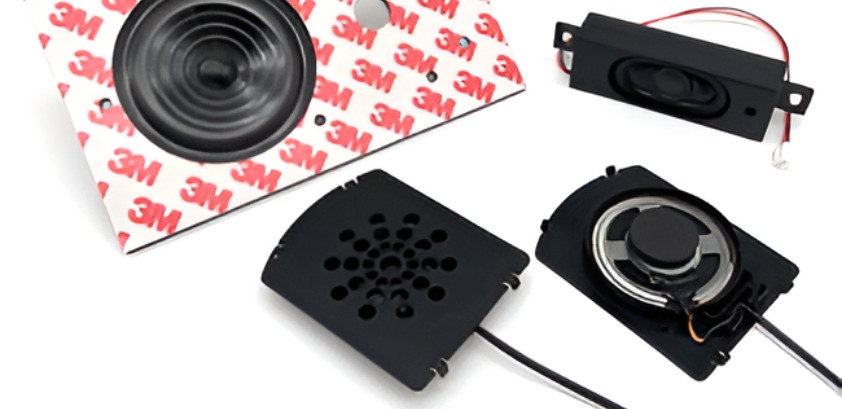
Acoustic signaling devices are used to generate a tone or sound that is audible to humans. This is done by generating sound waves in the air through the membrane of a signal transmitter or loudspeaker. The sound waves themselves are fluctuations in air pressure. The rapid changes in air pressure are perceived by the human ear as sound or noise.
Sound waves and frequencies
There are long sound waves with a low frequency, which are perceived as low tones, and short sound waves with a higher frequency, which are perceived as high tones. The frequency defines the number of vibrations per second.
The audible range for humans is 16-21Hz for low frequencies and 16,000-20,000Hz for high frequencies.
The height of the sound wave determines the volume. The most sensitive or sensitive range of the human ear is between 2,000-5,000Hz.
This is why most acoustic signaling devices are designed for this frequency range.
Our types of audible signaling devices
Magnetic or electrodynamic signaling devices, often also called transducers
The structure of the magnetic signal transmitter is relatively simple. A fixed coil is located in a permanent magnet. The magnetic field is bundled by an iron core fixed in the center. Above this is a freely movable membrane. If an alternating voltage is now applied, the magnetic field changes accordingly. The membrane is moved up and down, which ultimately produces the sound. The sound frequency changes depending on the alternating frequency. Each signal transmitter has a resonance frequency (see manufacturer's specifications) at which the signal transmitter generates the highest sound level; also abbreviated to SPL (sound pressure level). If the signal transmitter is controlled with an asymmetrical square wave voltage, the correct polarity must be ensured.
Electrodynamic signaling devices with resonant circuit
There are also electrodynamic signaling devices with built-in electronics, known here as resonant circuits. The term buzzer is often used in this context. If a DC voltage is applied to the buzzer, the membrane starts to vibrate and produces a sound. In this case, the resonant circuit is already tuned to the resonant frequency of the signal transmitter. Particular attention must be paid to the manufacturer's voltage specifications and the correct polarity.
In simple terms, the principle of the piezo signal transmitter is based on the directional deformation of a piezoelectric material. For this purpose, a brass disk is usually firmly bonded to a ceramic disk with a smaller diameter on one side.
When an alternating voltage is applied, the disk deforms and bends in one direction and then back again. This change follows the frequency of the alternating voltage and thus produces a sound. As the frequency range is rather narrow, piezo signal generators are preferably used to reproduce a frequency with high sound pressure. The piezo disk is therefore less suitable for use in speech or music reproduction. If the piezo disk is installed in a housing, this system is often referred to as a piezo transducer.
Piezo transducers and their variants
There are also piezo transducer systems that have built-in electronics, known here as a resonant circuit.
This means that a simple DC voltage source is sufficient to make the piezo transducer vibrate. The term piezo buzzer is often used in this context.
Piezo signal generators with a feedback electrode offer the great advantage that the piezo disk is operated at its resonant frequency in this oscillating circuit, thereby generating the highest possible volume.
When a DC voltage is applied, the metal disk deforms. This also generates a voltage in the feedback electrode, which in turn controls the resonant circuit and tunes it to the resonant frequency.
Mechanically constructed buzzers and receiver ear units
When it comes to producing the lowest possible tone in the 400Hz range, the best way to do this is with a mechanically constructed buzzer. The principle is quite simple. A magnetic field is generated by the coil L1. This moves the so-called hammer made of iron. The movement is detected in coil L2 and the transistor switches. The oscillating circuit synchronizes and the hammer strikes the diaphragm evenly, producing a very distinctive buzzing sound.
Basically, a receiver ear unit can be described as a modified loudspeaker. Specially developed for telecom applications to achieve the flattest possible frequency curve without peaks when the receiver ear unit is held close to the ear. The term receiver is often used in this context. The receiver ear unit is optimized for the frequency range between 300-3400Hz. Nowadays there are different designs and sizes from 10mm to 38mm in diameter.
Microphones: How they work
The microphones that are important for voice transmission today are usually electret or condenser microphones. Here, sound waves are converted into electrical impulses.
An electrically conductive diaphragm is mounted closely in front of a metal plate. The membrane is mounted in such a way that it is electrically insulated. The metal plate is electrically pre-charged. The so-called "freezing" of the electrical charge, also known as electrostatic polarization, has only become possible with an electret foil. This is permanently applied to the metal plate. As a result, the membrane is sufficiently biased so that only a low voltage of around 1.5V is required to generate a potential gradient and to supply the FET (field effect transistor) with voltage. This FET then amplifies the power. If a sound hits the membrane, this leads to a change in capacitance between the membrane and the metal plate. These capacitance fluctuations can then be measured at the output as a voltage fluctuation.
This voltage fluctuation can then be transmitted via a cable and made audible again via a loudspeaker using an amplifier.
The microphones have been optimized for different applications.
Directional characteristic of microphones
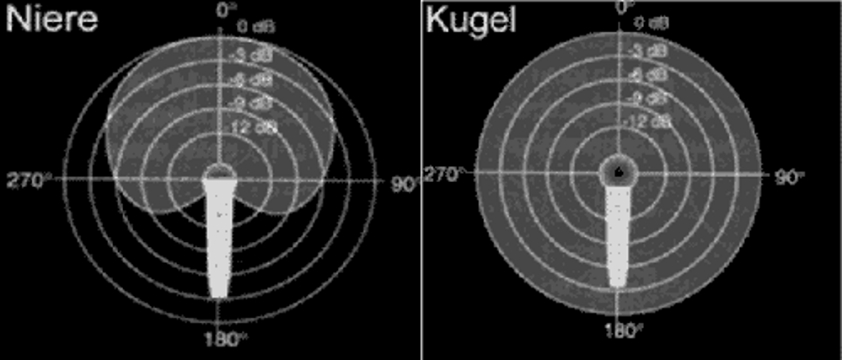
The directional characteristic indicates the sensitivity of a microphone depending on the angle of incidence of the sound. The reference is the 0-axis as the main sound source. The directional characteristic is illustrated by directional diagrams. The directional characteristic is not the same over the entire frequency spectrum, but changes depending on the frequency. For this reason, the directional diagrams show the characteristic uniformly at 1kHz. Basically, it can be said that the directional characteristic is significantly less pronounced at low frequencies than at high frequencies.
Differences between omnidirectional and cardioid polar patterns
There are two main directional patterns: omnidirectional and cardioid.
With the omnidirectional characteristic, the sound is received equally from every direction, which is why the term omni directional is often used. In contrast, the cardioid characteristic only converts sound from the front. On the rear axis (180°) there is theoretically almost 100% attenuation, apart from reflections. In practice, the attenuation is around 20-35dB. The cardioid characteristic of a microphone is often referred to as uni-directional.
MEMS microphones: Powerful microphone for high demands
The MEMS microphone is a particularly powerful microphone for high demands and with small dimensions. MEMS stands for Microphone Electronics Mechanical System. As with other microphones, sound pressure is converted into electrical signals.
Depending on the design, the sound signal is converted into a corresponding analog output voltage or into a digital pulse density modulated (PDM) output signal.
Sound is converted into electrical signals by changing the coupling capacitance between a fixed base plate and a movable plate (diaphragm).
The sound hits the membrane and sets it in motion. This changes the air gap and thus the capacitance between the base plate and the diaphragm plate.
The compressed air in the rear chamber can escape through the pressure equalization opening, allowing the diaphragm to move. The electrical signals are then amplified by an ASIC chip.
A directional characteristic as omni or uni-directional microphone is achieved by appropriate RF noise canceling filters.
There are microphones whose designs have the sound opening at the top of the housing or in the base plate.
The advantages of a MEMS microphone
- High sensitivity of up to -26dB
- Signal-to-noise ratio > 60dB
- Small design of about 3x4mm and 1mm height
- Reflow solderable
- SMD mountable
- Wide temperature range from -40°C to +100°C
About TPi-electronic components GmbH
TPi-electronic components GmbH sees itself as a bridge between the production lines in Asia and the manufacturing industry here on site. As an independent supplier of electronic components with a focus on acoustics, printed circuit boards, batteries and cable assembly, the company stands for competence and reliability.
Our mission and values
Our goal is to produce electronic components cost-effectively in Asia and to offer them according to the individual requirements of our customers. To be successful, it is not only the product that counts, but also respect and tolerance towards other cultures. The "how" of communication among each other and the personal will of each individual are the basis for economic success.
Our founding history and partnerships
The company was founded at the end of 2004. The management can look back on many years of experience. The result today is a network of carefully built up cooperations with Asian partners.
Through continuous exchange at eye level and regular visits to the production facilities, a trusting and friendly cooperation has been established.
Project process
Contact
You/new customers contact us via the website or by e-mail and
describe what is required.
Analysis
TPi contacts you by telephone to analyze your requirements and specifications in detail.
Proposed solutions
The information collected is used to present the (new) customer with proposed solutions.
Prototype
As soon as a product has been defined for the project, a sample is produced for the customer to test in the prototype.
Defining the framework conditions
Once the sample has been approved, the framework conditions for further cooperation are discussed, which ultimately forms the basis for the final offer.
Project completed
The project is then successfully implemented and completed.
E-Mail request
Do you need electronic components for your project? Then please fill out our contact form and we will get in touch with you as soon as possible. If possible, please state directly which components you are interested in and the desired quantity.